The Challenge
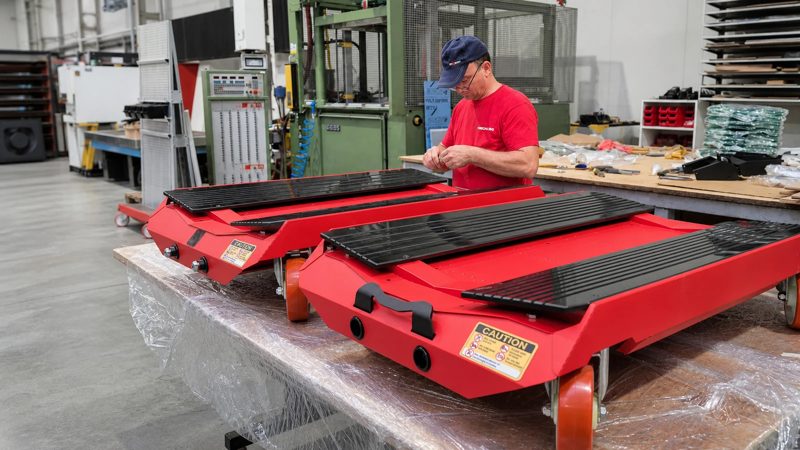
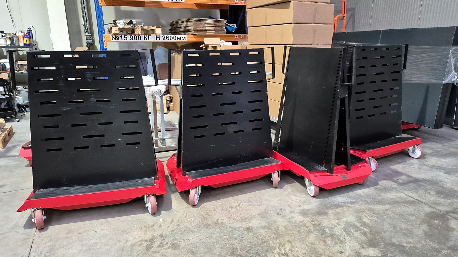
NEON SMART is an industrial transport cart for sheet material — sturdy, with a low centre of gravity and a load capacity that stands up to daily work in a production environment.
The chassis is not assembled from standard profiles. It is made of many purpose-designed parts, laser cut, bent and welded to one another.
The parts were designed from the outset to locate one another through technological holes and joints. That makes assembly easier and keeps the geometry repeatable.
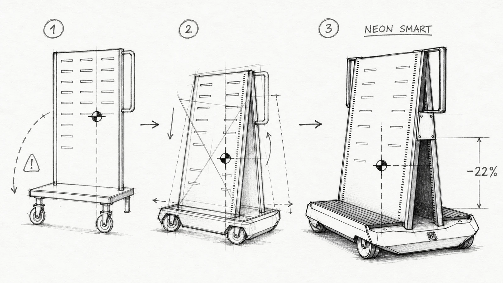
The design didn't start from a finished idea. NEON SMART went through three successive versions — from a conventional tall trolley to the final form with wheels housed inside the body and a 22% lower centre of gravity.
But once it is assembled, the most labour-intensive operation is still ahead.
The lower part of the chassis alone contains over 250 welds. The upper structure adds more than 50. One finished cart therefore takes over 300 separate welding operations.
- 300+welds per unit
- 2rotating jigs
- 360°positioning
- 3 → 24carts: from three a shift with two welders to twenty-four in half a shift
Engineering Approach
The first stage — prototyping
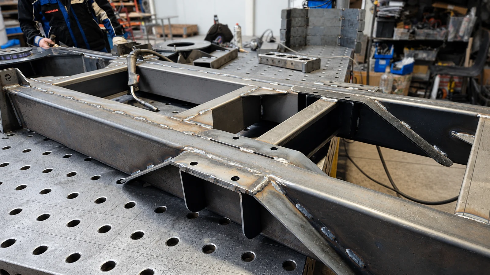
The first few dozen carts were made and welded by hand.
That was not a compromise but a necessary stage. In prototyping you change parts, holes, bends, weld positions and the assembly sequence — quickly and without spending on tooling.
Here the advantage of having different technologies in one place was decisive. The structure is designed, the parts are laser cut, bent, assembled and welded. The finished prototype goes for testing in real conditions. After the tests the corrections go back into the engineering model and the next version is produced.
That is the right approach for a prototype. But not for a series.
When the prototype became a product
Once the structure had proven itself, the task changed.
We were no longer looking for a way to make one cart. We had to make dozens of identical ones, with consistent quality, predictable time and controllable cost.
At over 300 welds per unit, manual welding became the main constraint.
Two welders produced about three carts in one working shift.
The next engineering step was obvious.
The robotic cell
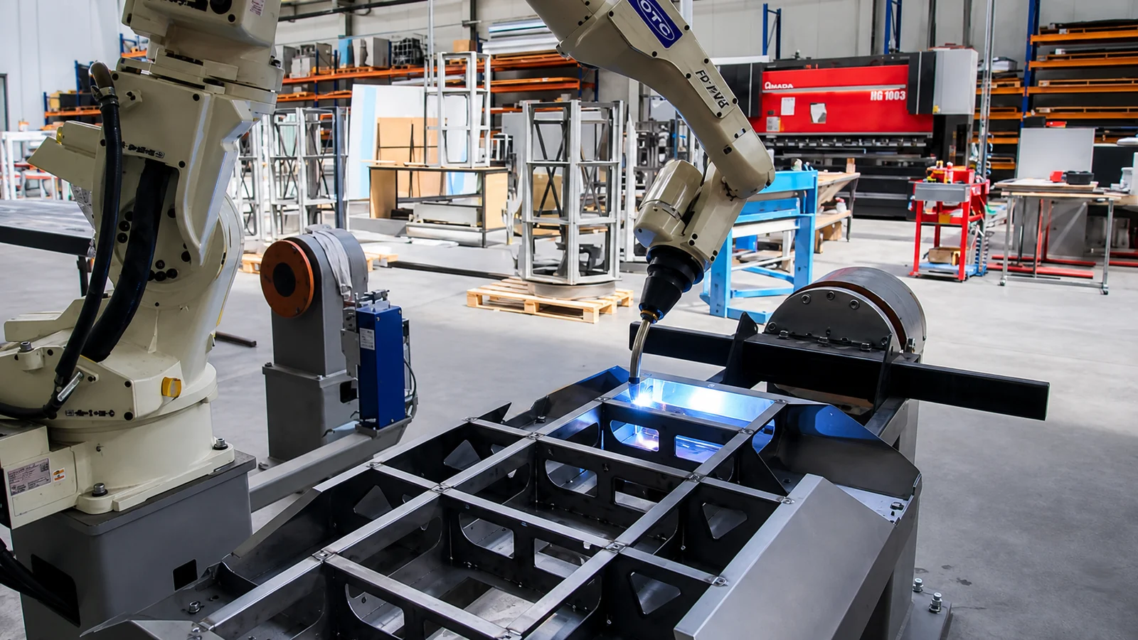
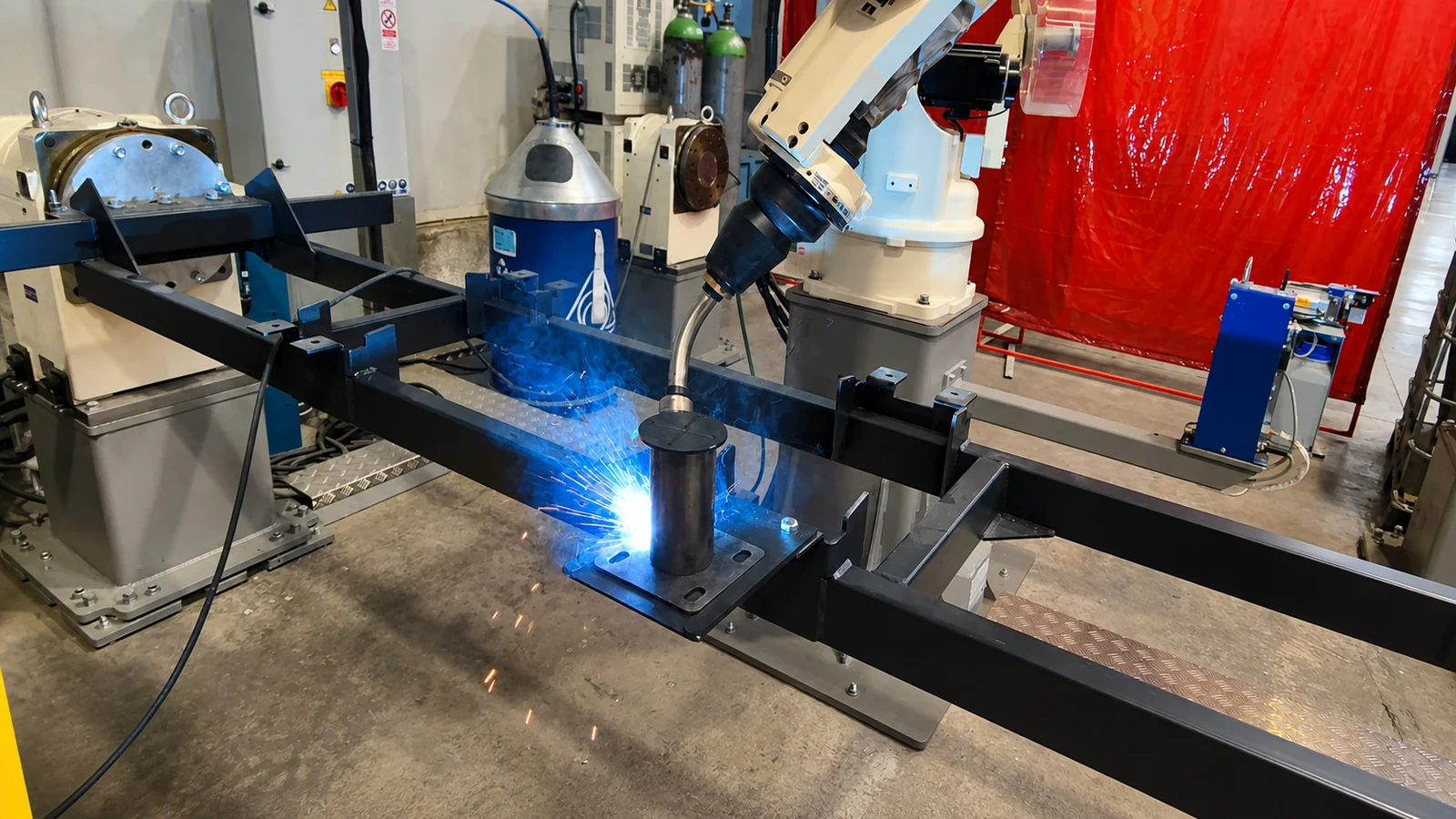
For series production we brought in an OTC FD-B4LS robotic system.
The robot has seven axes of movement. Two rotating positioners are integrated with it, each with a load capacity of 500 kg and 360° rotation.
That matters particularly with a structure like NEON SMART. Instead of the robot being limited to the welds reachable from one position, the part is rotated automatically during the program.
The robot welds a given zone. The positioner turns the chassis. The robot carries on with the next welds. The torch reaches every side of the complex three-dimensional structure without the operator turning the heavy part.
Two jigs — the robot welds, the operator prepares
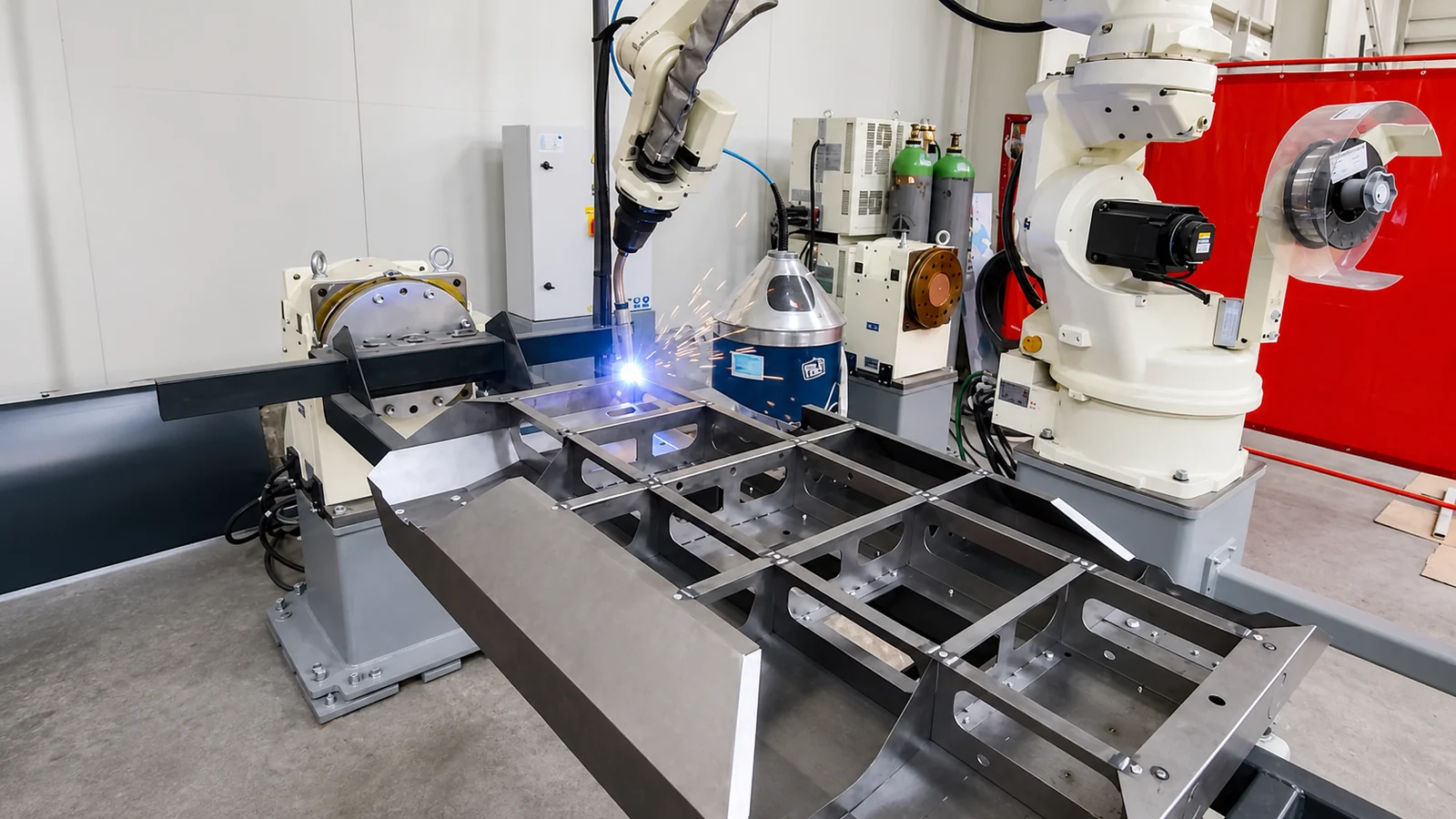
The most important feature of the cell is not the robot itself but the organisation around it.
While the robot welds on one side, the operator works on the other. They release the finished part, load the next set of components and clamp the new structure into the jig.
When the robot finishes, the system moves to the part prepared on the other side. One side welds. The other prepares the next.
The human and the robot do not perform the same operation. Each does what they are better at.
The robot does not count on a perfect part
In real series production there is a factor that often gets underestimated.
A welded structure is never the perfect CAD model. There are tolerances from laser cutting and bending, small deviations in assembly, distortion from the process itself.
That is why the system has tactile search. Through the welding wire the robot touches predefined reference points and holes on the part. Before certain operations it checks where the part actually is and compensates for the real position against the programmed one.
That is the difference between automated movement and a real robotic process.
Engineering Note
Automation starts at the design stage
The most important conclusion from this project is not that the robot welds faster.
Robotisation starts much earlier. At the design stage you already have to decide how the part will be cut, how it will be bent, how the components will locate one another, how they will be clamped in the jig, where the welds have to be, how the robot will reach them, how the part will be rotated, how the operator will load it.
When those questions are settled in the engineering phase, the robot is not a separate machine at the end of production. It is part of the way the product was designed.
Process Route
Idea → 3D design → prototype → laser cutting → bending → manual assembly and welding → testing → optimisation → dedicated jigs → robotic welding → series production.
The prototype proves the idea. Automation turns it into an industrial product.
Result
Today the robotic cell welds twenty-four carts in half a machine shift.
For comparison: before robotisation two welders produced about three carts in a full shift.
But throughput is only part of the result. We also get:
- High repeatability on every weld
- Consistent quality from unit to unit
- Predictable production time
- Controllable cost
- The capacity for significantly larger series
- Less dependence on manual welding labour
Do you have a product that needs to move from prototype to series?
Send us a 3D model, a drawing or a description of the task. We will assess which stage of the process is worth automating, and when.


